An increasing amount of decisions must be taken early, based on digital models. RD&T is the tool.
The software tool RD&T (Robust Design & Tolerancing) applies statistical variation simulation for tolerance analysis, which allows the effect of manufacturing and assembly deviations to be simulated and visualized long before any physical prototypes are being made. Different design concepts can thereby be analyzed and compared and the quality of the decisions made can be improved. RD&T is a software package that supports the geometry assurance process in all its phases, from early design and styling to pre-production and production. A strong focus is on making the product concept robust to manufacturing variation and being able to predict final variation in the product’s critical dimensions. RD&T has been used in the automotive industry for over 20 years, supporting both OEMs, suppliers, and consultants. It is based on research and is at the forefront, especially for non-rigid (compliant) analysis.
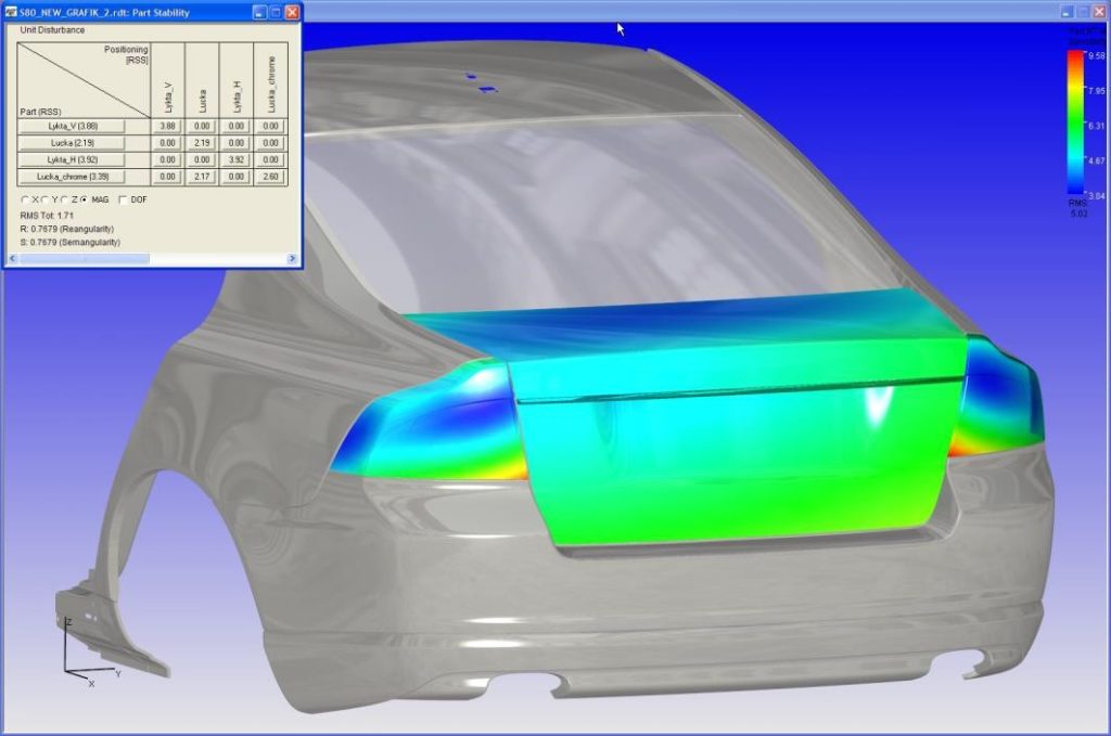
In early design phases, the robustness of the design and assembly concept can be analyzed and evaluated using stability analysis. The stability analysis determines the geometrical sensitivity due to position of locators. Locator positions can be manually or automatically optimized with respect to critical areas or overall sensitivity.
Statistical Variation Simulation
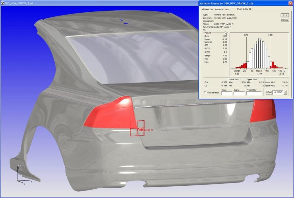
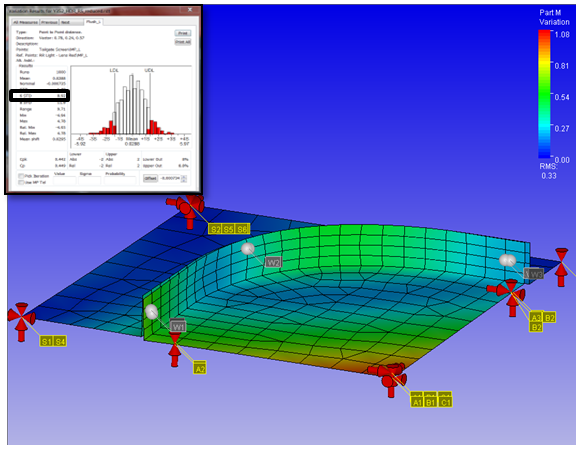
Monte Carlo simulation is used in RD&T for tolerance analysis, to statistically analyze variation, capturing all 3D effects and interactions for complex assemblies. RD&T has an integrated FEA (Finite Element Analysis) solver that allows non-rigid (compliant) analysis. The effect of variation can then be analyzed for assemblies with sheet metal or plastic parts that bend or deform during assembly. This module also allows assembly, welding, and clamping order to be analyzed and optimized to minimize variation.
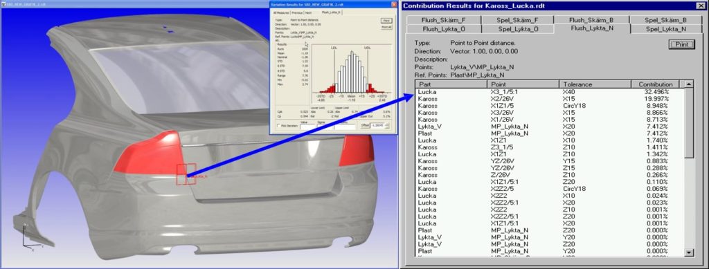
Contribution Analysis
Contribution analysis is used to identify the relative contribution from each tolerance contributing to variation in a critical dimension. A ranked list presents the relative importance of each tolerance. The contribution analysis allows the user to identify what tolerances to tighten and what tolerances can be widened.
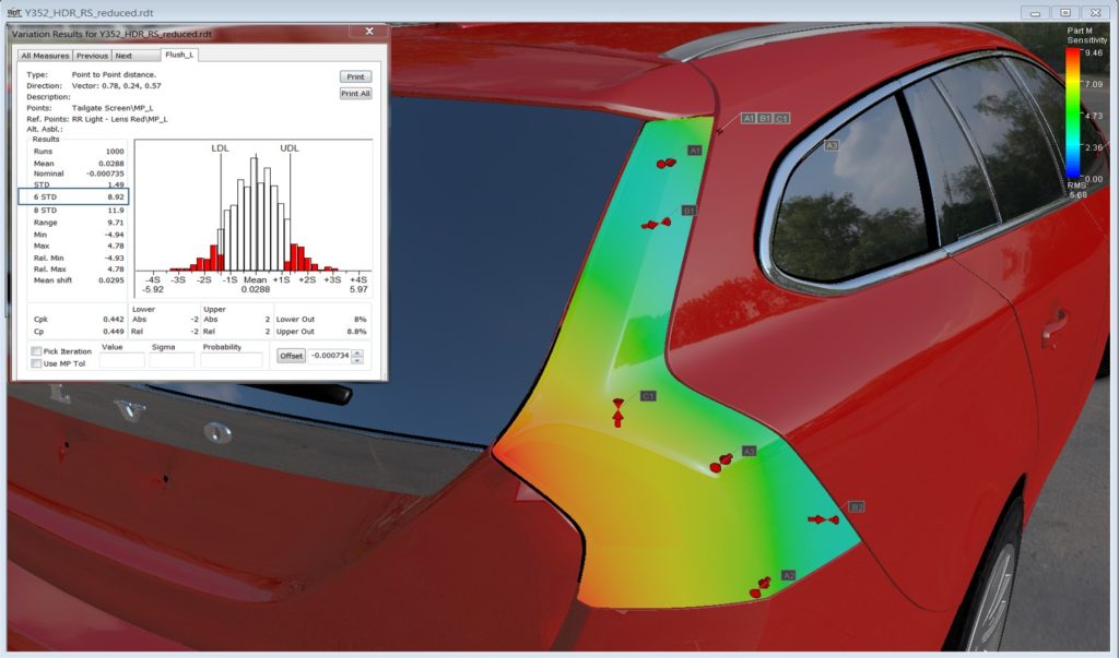
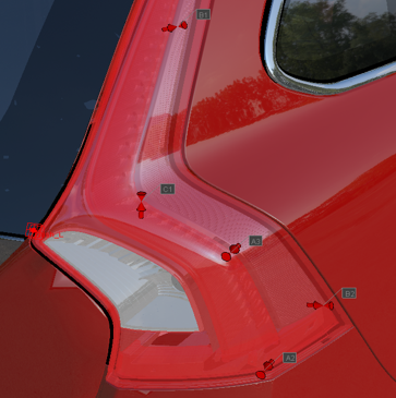
High-End Tolerance Visualization
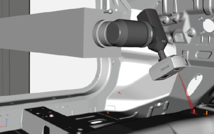
In the RD&T showroom, tolerances and the effects of variation can be visualized with high degree of realism by adding lighting, shadows, textures and material properties. RD&T has also an interface with some of the leading visualization software packages on the market. The visual sensitivity of the product can then be judged with respect to geometrical variation long before production takes place and unnecessary late changes can be avoided.
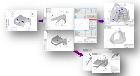
Engineering Documents
A full documentation suite supports the geometry assurance process from requirement definitions, master location systems definitions, simulation results, matching & trimming, and inspection preparation.
The standard document suite is generic to fit a range of business areas but can also be customized on demand.
Modules
RD&T Module for non-rigid simulation
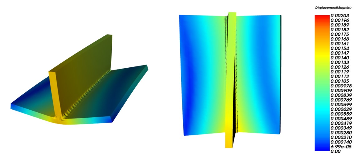
The non-rigid (compliant) simulation module in RD&T is an FEA-based module that allows elastic behavior to be included in the simulations. Elastic behavior can typically occur during the use of the product or during assembly, when non-nominal parts are clamped in a fixture, forced together by for instance spot-welding, and then released.
RD&T uses an embedded FEA solver that allows for fast and accurate simulation without any data transfer or need for interfaces to external software.
The non-rigid simulation module has an automatic contact detection functionality. This important feature allows detection of unforeseen contacts between parts due to geometrical deviations. The resulting contact forces are automatically included in the calculations.
Non-rigid simulation in RD&T allows effects of forces, bending, gravity, spring-back, joining sequence and heat to be included in the simulations to enhance accuracy. The simulations can be combined with various optimization strategies for locator and joining sequence optimization.
Non-rigid variation simulation can be used in early design phases to optimize the product and assembly concept but also serve as a digital twin in a real-time control loop.
RD&T Module for inspection preparation
Module for the definition of inspection points, generation of inspection drawings, and PKI documents (company-specific). RD&T includes state of the art path planning from IPS to allow easy inspection preparation and automatic generation of collision-free and cycle time-efficient DMIS code with key benefits such as:
parameterized inspection rules
DMIS viewer
easy alignments and advanced constructions
supports twin inspection
easy feature accessibility analysis
minimizing probe configurations
automatic generation of collision-free motions
sequence optimization of cycle time
RD&T module for welding simulation (to be released)
Variation in the manufacturing process leads to component variation which, together with fixture variation and variation stemming from the joining process, propagates to the final product. Research has shown that the effect of welding on the final assembly is highly dependent on the variation in the individual parts and fixtures. To accurately simulate the geometric variation of an assembly, joined by weld joints, variation simulation and welding simulation need to be performed in combination. Therefore, RD&T has an embedded module for welding simulation that can be combined with the statistical Monte Carlo simulation to predict a realistic outcome of the assembly variation. RD&T supports full transient simulation as well as a number of simplified methods that give good results with reduced calculation time. Both spot-welding and continuous welding are supported.
Additional RD&T modules, provided by demand
Envelope calculation: Calculation of variation or motion envelope for packaging analysis.
Virtual matching: Calculates trimming/adjustment of locators to compensate for form errors.
Root cause analysis: Identifies errors in individual fixtures/locators based on inspection data on product level.